

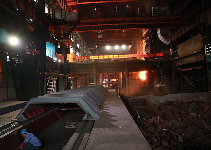
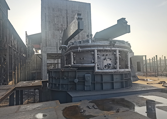
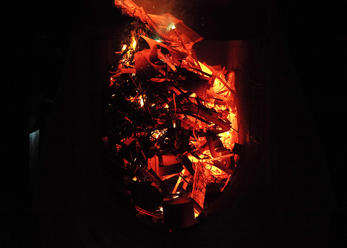
The continuous charging electric arc furnace technology is currently the most advanced, clean, energy-efficient, and environmentally friendly steelmaking technology. This process can preheat the scrap steel in the conveying trough, saving electrical energy while improving the working environment. Unlike basket charging, it eliminates secondary smoke and dust generation. Meanwhile, the primary flue gas leaves the preheating section at a high temperature after preheating the scrap steel, ensuring complete combustion of any pollutants in the smoke and dust and avoiding the production of odorous gases.
The smelting bath of the continuous charging electric arc system is stable, significantly reducing the impact on the power grid compared to electric furnaces with basket charging. Compared with other furnace types, the continuous charging technology can reduce noise in the workshop and significantly improve the working environment. As an efficient technology, it can reduce the investment in electric furnaces, substations, bag filters, and smelting equipment, while improving the overall efficiency of the workshop.
Main Technical Parameters of the Electric Arc Furnace
| Parameter | Value |
| Rated Capacity | 70 T |
| Average Tapping Weight | 70 T |
| Maximum Tapping Weight | 70 T |
| Inner Diameter of Furnace Shell | 5600mm |
| Diameter of Graphite Electrode | Ø550mm |
| Rated Capacity of Transformer | 56MVA |
| Annual Operating Time | 330 days |

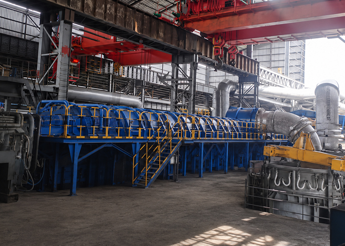
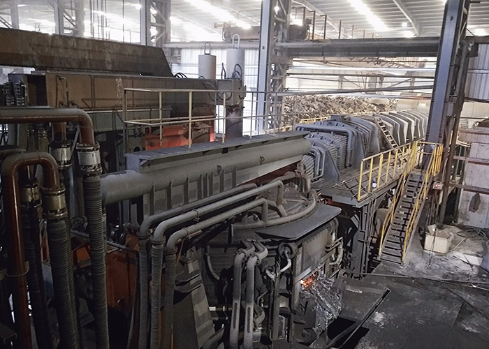
Main Parameters of Horizontal Continuous Charging Device
| No. | Name | Unit | Value |
| 1 | Feeding Conveying Capacity | t/h | 350 |
| 2 | Feeding Time | min | ~35 |
| 3 | Maximum Scrap Feeding Speed | m/min | Approx. 5.5 |
| 4 | Maximum Speed of Connecting Trolley | m/min | 6 |
| 5 | Vibration Frequency of Connecting Trolley | Hz | 4.33 |
| 6 | Adjustable Range of Conveyor Vibration Frequency | Hz | 2.5-5 |
| 7 | Horizontal Amplitude | mm | 20-28 |
| 8 | Vertical Amplitude | mm | 0 |
| 9 | Total Length of Equipment Layout (From Furnace Center to Equipment Tail) | m | ~59.486 (Subject to confirmed drawings) |
| 10 | Internal Cross-Section Dimension of Conveyor | mm | 2000×1000 |
| 11 | Internal Cross-Section Dimension of Trolley Chassis | mm | 2258×980 |
| 12 | Vibration Motor Power of Conveyor: Motor Power of Tail Vibrator | kW | 110 (Frequency Conversion Speed Regulation) |
| 13 | Vibration Motor Power of Trolley | kW | 37 |
| 14 | Dynamic Seal<br>- Wind Pressure<br>- Air Volume<br>- Motor Power | Pa<br>Nm³/min<br>KW | -276<br>Approx. 30000<br>11 |
| 15 | Hydraulic System<br>- System Pressure<br>- Working Medium | -<br>MPa<br>- | Hydraulic source provided by the electric furnace hydraulic station<br>12<br>Fatty Acid Ester Hydraulic Oil |
| 16 | Opening Dimension of Furnace Shell | mm | To be confirmed by the electric furnace manufacturer (Subject to confirmed drawings) |
| 17 | Scrap Charging Height | mm | Approx. ~600 |
| 18 | Water Cooling System<br>- Inlet Water Pressure<br>- Return Water Pressure<br>- Inlet Water Temperature<br>- Return Water Temperature<br>- Cooling Flow Rate<br>- Emergency Flow Rate | MPa<br>Mpa<br>℃<br>℃<br>m³/h<br>m³/h | 0.5-0.6<br>0.2-0.3<br>≤35<br>≤55<br>700<br>300 |
| 19 | Scrap Specific Gravity | T/m³ | 0.5-1.0 |


Equipment Supply Scope (Single Unit)
| No. | Name | Quantity | Main Material |
| 1 | Hood System | 1 set | Steel adopts genuine Hansteel products |
| Water-Cooled Hood | 1 set | 20g seamless steel pipe Φ89*10 | |
| Insulation Hood | 1 set | Composite hood | |
| 2 | Ladders, Platforms, Railings and Supports | 1 set | Q235-A profile welded structure |
| 3 | Water-Cooled Trough | 1 set | Henan QS |
| Trolley Water Cooling | 1 set | 16Mn, 16mm | |
| Water-Cooled Trough in Preheating Section | 1 set | 20g, 16mm | |
| 4 | Feeding Trolley | 1 set | Henan QS |
| Trolley Vibrator | 1 set | Shell: 15CrMo; Gear: 35CrMo; Shaft: 40CrMnMo; Bearing: SKF | |
| Trolley Bracket | 1 set | 20g, 16mm, 12mm | |
| Bearing Temperature Monitoring System | 1 set | Henan QS | |
| Trolley Support and Moving Device | 1 set | 40Cr, 20g, 20mm, 12mm; ZG35 | |
| Trolley Vibration Drive Device | 1 set | Motor: YE3-250M-6 37KW; Manufacturer: Wannan Electric Machinery Factory | |
| Hydraulic Cylinder | 1 set | Huafeng Hydraulics | |
| Limit Switch Assembly | 1 set | Schneider | |
| 5 | Tail Conveying System | 1 set | – |
| Feeding Section Trough | 1 set | 16Mn, 25mm | |
| Loading Skirt Support Device | 1 set | Q235 | |
| Tail Vibrator | 1 set | Shell: 15CrMo; Gear: 35CrMo; Shaft: 40CrMnMo; Bearing: SKF | |
| Tail Vibrator Drive Device | 1 set | Motor: Y315L2-8 110KW; Manufacturer: Wannan Electric Machinery Factory | |
| Centralized Lubrication System | 1 set | Qidong Lubrication | |
| Bearing Temperature Monitoring System | 1 set | Henan QS | |
| Preheating Section Base Support | 1 set | 20g, 12mm | |
| 6 | Dynamic Seal Device | 1 set | Henan QS |
| Axial Flow Fan | 1 set | Nantong Axial Flow Fan | |
| 7 | Scrap Pressing Mechanism | 1 set | Henan QS |
| Hydraulic Cylinder | 1 set | Huafeng Hydraulics | |
| 8 | Water Cooling System | 1 set | Q235 |
| 9 | Electrical Control System | – | Henan QS |
| 10 | Detection System | – | Shanghai Instrument Factory |
| 11 | Lubrication System | – | Qidong Lubrication |

Water Cooling System
The total water cooling interface of the horizontal charging equipment is provided 1 meter outside the equipment.
Hydraulic System
The hydraulic source is provided by the electric furnace hydraulic station.
Electrical Control System
The power supply for continuous charging is provided by the workshop. The control cabinet and operation platform are placed in the electric furnace control room, where a reserved space is available. A reserved communication interface is provided between the charging equipment and the electric furnace.
Dust Removal System Interface
The demarcation point of the horizontal charging dust removal system is the flange surface of the hood interface of the horizontal feeding system. Party B shall provide the requirements for the flue interface (including the matching flange).
Equipment Foundation
Party A is responsible for the civil engineering design, construction, and fabrication of the equipment platform (concrete). Party B shall provide the data required for the factory design of the equipment (including basic condition drawings, load, and other basic data). Party A is responsible for the supply and construction of embedded steel plates, embedded pipes, and anchor bolts in the foundation.

1.1 Preheating Hood System
The hood in the preheating zone consists of a water-cooled hood, an insulation hood, and an outlet hood. The water-cooled hood is welded with seamless steel pipes, while the insulation hood and outlet hood adopt composite hoods. A flue gas temperature measuring device is installed on the outlet preheating hood.
1.2 Ladders, Platforms and Supports
The support frame platform is used to support the water-cooled hood and composite hood in the preheating zone. It is composed of I-beams, channel steels, steel plates, railings, etc.
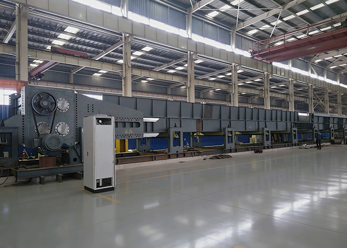
1.3 Preheating Section Trough
The preheating section trough includes a trolley water-cooled trough and a preheating trough. The water-cooled trough is welded with heat-resistant steel plates, and its bottom is stepped to facilitate scrap preheating. The trolley water-cooled trough extends into the electric furnace body during charging. Due to the high ambient temperature inside the furnace body, the water-cooled channel at the discharge end adopts a seamless steel pipe type to prevent weld cracking caused by local heating at the end of the discharge end.
The preheating conveying device is located in the middle of the conveyor and consists of a conveying trough, side plates, bottom plate, connecting beams, support beams, and other components. It adopts fitted bolt connections, and the side plates, bottom plate, and connecting beams are connected by ring groove rivets to prevent deformation caused by scrap impact. The feeding section trough is connected to the side plates by bolts.
A cooling water channel is arranged in the conveying trough, and circulating water is introduced during operation to prevent thermal deformation of the conveying trough.
The support device is composed of a bracket, convex base plate, concave base plate, high-strength double-ended bolts, etc. It adopts a single suspension assembly to support the vibrating conveyor beam, which is suspended on the bracket through the convex base plate, concave base plate, and high-strength double-ended bolts, enabling reciprocating swing during operation.
1.4 Tail Conveying System
The tail conveying system is composed of a vibrating conveyor beam assembly, a feeding section trough, a support device, etc.
The vibrating conveyor beam assembly consists of a tail vibrator connecting plate, side plates, bottom plate, connecting beams, support beams, and other components. The tail vibrator connecting plate is connected to the tail vibrator by fitted bolts, and the side plates, bottom plate, and connecting beams are connected by ring groove rivets to prevent deformation caused by scrap impact. The feeding section trough is connected to the side plates by bolts.
The support device is composed of a bracket, convex base plate, concave base plate, high-strength double-ended bolts, etc. The support suspension assembly is used to support the vibrating conveyor beam, which is suspended on the bracket through the convex base plate, concave base plate, and high-strength double-ended bolts, enabling reciprocating swing during operation.
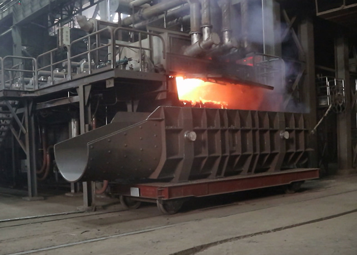
1.5 Vibrating Connecting Trolley
A vibrating connecting trolley is installed at the discharge end of the preheating zone. A hydraulic cylinder is installed at the rear of the trolley, and a water-cooled chassis is installed on the trolley. In the normal extended position, the water-cooled chassis on the trolley extends into the furnace. When the water-cooled chassis needs to be pulled out of the furnace, the hydraulic cylinder retracts, moving the trolley backward and holding it tightly.
The vibrating connecting trolley is composed of a frame, connecting frame, support suspension assembly, wheel assembly, transverse damping device, longitudinal damping device, hydraulic cylinder, limit switch assembly, etc.

1.6 Vibrator and Drive Device
The tail vibrator and trolley vibrator are parallel shafts driven by different inertias, connected to the feed end of the mounting frame through a drive joint. Four parallel shafts are installed in the vibrator, including a pair of high-speed shafts rotating in opposite directions at the same speed, a pair of low-speed shafts rotating in opposite directions at the same speed, a box body, a gear set, a lubrication system, etc. The rotation frequency of the two pairs of main shafts of the vibrator is fixed at 2:1 to generate composite harmonic vibration, enabling the vibrating conveying system to obtain differential motion characteristics. These four shafts are installed in a common cover, and gear transmission ensures synchronization between them.
Lubricating oil is contained in the gearbox to lubricate the gears, and all bearings are lubricated by a centralized lubrication system.
The vibrator adopts special large-clearance bearings for vibration machinery (SKF bearings), lubricated by a centralized oil-gas lubrication system, with a continuous operation service life of 10,000 hours. Each bearing is equipped with a bearing temperature measuring device, and the temperature of each bearing can be displayed on the HMI interface of the computer control system. The vibrator drive device is composed of a motor, belt, pulley, pulley guard, motor base, etc.
The tail vibrator motor is a 110KW, 740rpm three-phase fully enclosed foot-mounted motor with a cooling fan. The motor speed is controlled by a frequency converter installed in the MCC.
The motor power of the connecting trolley vibrator is approximately 37KW, and the motor is a fully enclosed type with fan cooling.
1.7 Dynamic Seal Device
The dynamic seal is installed at the end of the continuous charging preheating section. Its function is to generate an air curtain to prevent electric furnace flue gas from entering the atmosphere and atmospheric air from entering the dust removal system.
The negative pressure formed by the air absorbed by the dynamic seal fan is slightly lower than that formed by the main fan of the dust removal system, with a negative pressure value of -276Pa at the interface.
Since the negative pressure caused by the main fan of the dust removal system changes according to the electric furnace operating conditions, the negative pressure at the dynamic seal is also controlled by a frequency converter, which is automatically controlled by the automation system.
The dynamic seal device is composed of a dynamic seal base frame, preheater baffle, scrap pressing mechanism, mechanical fingers, axial flow fan, fan motor, hydraulic cylinder, gas temperature measuring device, gas pressure measuring device, etc.
1.8 Feeding Section Trough
The feeding section trough is located on the vibrating conveyor beam, behind the water-cooled chassis, and serves as a receiving trough for scrap fed by the user’s electromagnetic crane.
The feeding section trough is processed from steel plates. Due to the severe impact and wear on the trough body during feeding, the bottom plate of the conveying trough adopts a 25mm-thick high-strength wear-resistant steel plate.
1.9 Loading Skirt
The loading skirt is located behind the dynamic seal and is a steel structure component.
1.10 Water Cooling System Equipment
The equipment’s water cooling system is a closed-loop water supply system. The parts requiring cooling include the water-cooled hood, water-cooled chassis, and connecting trolley water-cooled trough.
The water cooling system equipment is composed of pressure transmitters, electromagnetic flowmeters, temperature transmitters (PT100), metal hoses, various stainless steel flanged ball valves, flanged worm-driven hard-sealed butterfly valves, cooling water distribution pipeline system equipment, etc.
A pressure transmitter and thermal resistor (PT100) are installed on the main cooling water inlet pipeline. An electromagnetic flowmeter and thermal resistor (PT100) are installed on the main return pipeline. A metal hose and stainless steel flanged ball valve are installed on each cooling water branch.
1.11 Hydraulic System
The hydraulic supply of the hydraulic system is provided by the electric furnace hydraulic station. The working pressure is 12MPa, and the hydraulic medium adopts fatty acid ester hydraulic oil. The equipment has the following two actions:

2.1 Frequency Converters
Frequency converters are used to drive the tail vibrator motor and dynamic seal device motor:
2.2 Motor Control Center (MCC)
The MCC provides power supply and operation control for all motors of the charging system.
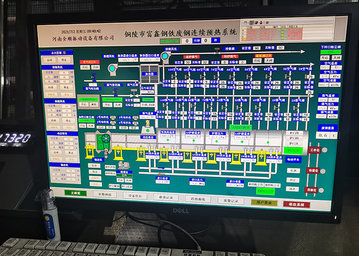
2.3 Continuous Charging Operation Console
The continuous charging operation console is installed in the electric furnace main control room and shared with the electric furnace control. It is mainly used for: starting and stopping the tail conveying device and connecting trolley; inlet and outlet of the connecting trolley; manual and automatic speed adjustment of the tail conveying device and connecting trolley; setting and displaying the speed of the conveyor belt and connecting trolley; and automatic adjustment of the seal device. The operation parameters are displayed through the HMI screen installed on the console, with important measurements displayed digitally.
2.4 Local Control Boxes
Local control boxes are installed near the main drive vibrator for local control of operating components,


| Client | Site | Technology | Year |
| Tangshan Iron and Steel Group Co., Ltd. | Tangshan City | CC EAF Technology | 2018 |
| Tongling Fuxin Steel Co., Ltd. | Tongling City | CC EAF Technology | 2019 |
| Liaoning Steel Plant | Liaoning Province | CC EAF Technology | 2020 |
| Indonesian steel mill | Indonesia | CC EAF Technology | 2022 |
| Shynkent Temir LLP | Kazakhstan | CC EAF Technology | 2024 |


